Flashing the Z8102AX router on Linux using a CH341A programmer (but not as planned)
I recently bought a ZBT Z8102AX-M2-T router on AliExpress straight from the manufacturer. I hoped to flash ROOTer on it to use it with a Quectel EM12-G LTE (cat. 12) modem for mobile broadband “home” Internet. Sadly, flashing following the instructions didn’t work, whether from factory OpenWrt or from U-Boot recovery.
Rather, troubleshooting and forum discussions (on Whirlpool ROOTer thread) all seemed to point out that flashing worked, but that the recent versions of this model had some hardware watchdog differences, causing it to reboot when not kicked correctly by the old software implementations.
Therefore, wanting to investigate that, I set upon myself to connect the serial port of the board, using serial for the first time in my life. Reading Dairyman’s “serial.pdf” (provided with every ROOTer firmware for our Z8102AX), it mentioned using a PL2303 USB-to-serial adapter. Looking, once again, on AliExpress, there seemed to be other chips with the same function (converting USB data signal to serial standards): FT232, ESP01, the forementioned PL2303, and CH341!
I remembered once buying a USB chip programmer that had this same chip! Maybe this could work? Turns out, yes. But not always. Let’s get to work.
Details and definition
- Hardware watchdog. Kicking the dog means sending a signal current to the watchdog to prevent it from sending a reboot signal. In this case, it seems the watchdog is kicked on the wrong GPIO pin. All this is far beyond my level.
- Serial: in this case, a very basic way of sending data, on by one (in serial, as opposed to parallel), on three cables (one for TX, RX and ground). When we talk about serial communications between hardware like microcontrollers, we generally use the UART protocol. We often think serial has to go through what we call a serial port (in reality a D-sub connector) which often uses the RS-232 protocol. It is still like that on many server or computers, but there are a lot of different serials standards and ports. Since serial is, in fact, so simple: the most important thing that changes between them is the baud rate (symbols per second), which can be set through software. To learn more, the “USB-to-serial adapter” Wikipedia page is nice because it doesn’t go as deep as, let’s say, the UART one.
- Whirlpool ROOTer thread: it has a lot of information if you dig through, more than on the ROOTer documentation. I use the archive version (on the bottom right of the page) combined with the browser search to look for keywords. Old school.
- CH341: some information here.
The programmer
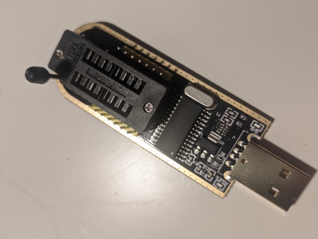
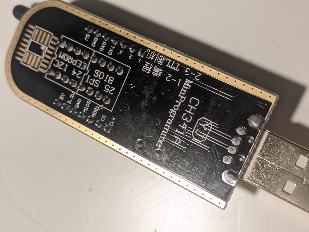
I bought this on AliExpress some time ago for flashing Libreboot on ThinkPads, which I never even did.
To use it for UART rather than for I2C/EPP/MEM (or whatever thing I don’t know about), remove the jumper between pin 1 and 2 (source).
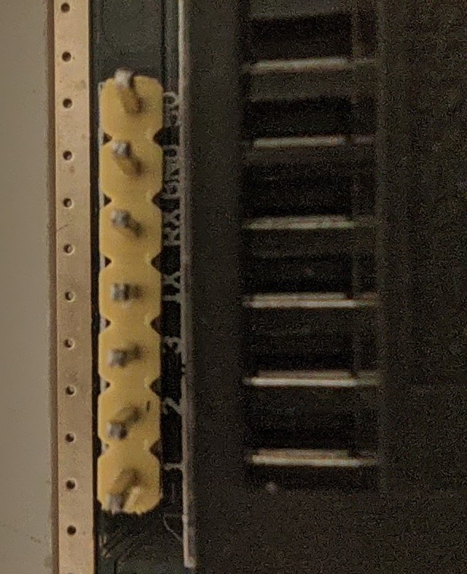 The serial pins with the jumper off. You can see TX, RX and GND
lsusb output, with the jumper:
Bus 001 Device 009: ID 1a86:5512 QinHeng Electronics CH341 in EPP/MEM/I2C mode, EPP/I2C adapter
Without the jumper:
Bus 001 Device 008: ID 1a86:5523 QinHeng Electronics CH341 in serial mode, usb to serial port converter
dmesg shows that the USB adapter now has an attachment at /dev/ttyUSB0:
[ 1878.530129] usb 1-1: new full-speed USB device number 11 using xhci_hcd
[ 1878.670774] usb 1-1: New USB device found, idVendor=1a86, idProduct=5523, bcdDevice= 3.04
[ 1878.670805] usb 1-1: New USB device strings: Mfr=0, Product=0, SerialNumber=0
[ 1878.674783] ch341 1-1:1.0: ch341-uart converter detected
[ 1878.675744] usb 1-1: ch341-uart converter now attached to ttyUSB0
Wiring to the router serial port
You need normal female-female jumper wires (you might call these GPIO or DuPont cable, and you will have some if you do Arduino or Raspberry Pi projects).
- Black goes on ground (GND).
- Green goes on receive (RX).
- White goes on transmit (TX).
- (I believe the red cable would go on 3.3 V, but we mustn’t use one here, otherwise risking damaging our router or adapter. The router will already be powered by its power supply.)
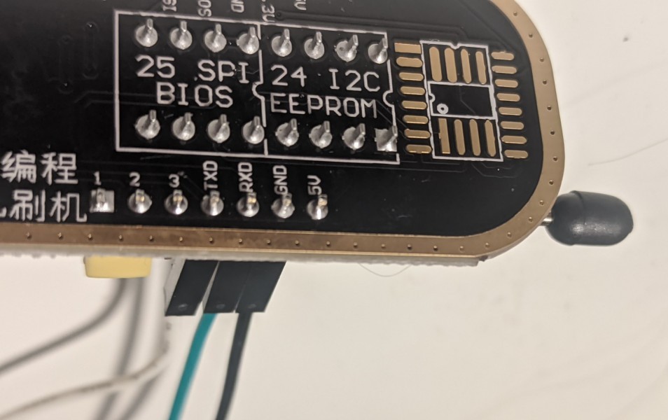 How the wires should be plugged in to the programmer
Do the same to the serial port on the router board. In some cases, like happened to me, you need to reverse the RX and TX cable there (green on TX and white on RX). Try it if you can’t see anything on your terminal software. Doing so won’t damage anything.
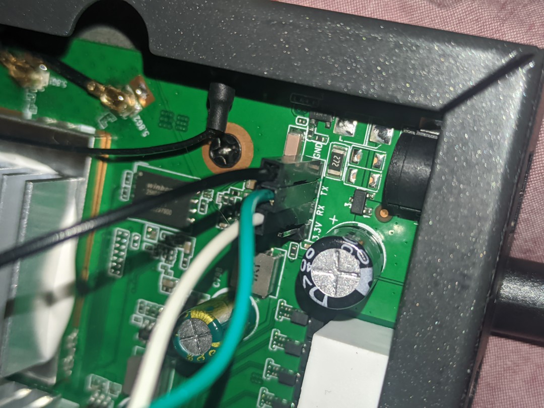 The serial pins on the router
Serial terminal emulators
On Linux 6.6.8-2, it seems I don’t need driver. If you do, here’s one, open-sourced by the manufacturer.
There are a lot of options for terminals and it can seem daunting. You need a terminal capable of displaying both received and sent data in the same window (like Hyperterminal, makes reading everything much, much, easier and feels more normal). I personally like using a GUI.
GTKTerm can be installed on Arch Linux through AUR and is available on Debian repositories.
Install it. Plug in the adapter. Open it (not before plugin the adapter). Go to “configuration”, “port”. Set the port to /dev/ttyUSB0 and the baud rate to 115200 (the joys of a GUI are here). Leave the rest as default. The bottom left should now show the open virtual serial port.
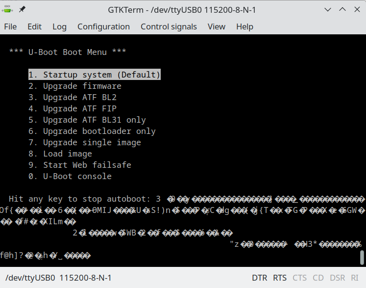
Plug in the router. Get to the boot dialog with options. Unplug the router if you want to have a look at it, because you only have 3 seconds before it frenetically scrolls. Press the key to select “Upgrade firmware” (here, 2). Press yes when asked if you want to run the firmware you will install (duh). And select TFTP as a load method (here, 0).
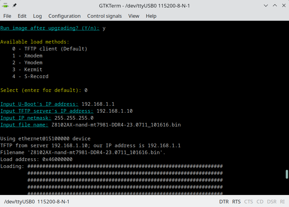
TFTP settings:
- Input U-Boot’s IP address: 192.168.1.1 (as is)
- Input TFTP server’s IP address: 192.168.1.10 (default 192.168.1.2 should work too)
- Input IP netmask: 255.255.255.0 (as is)
- Input file name: Z8102AX-nand-mt7981-DDR4-23.0711_101616.bin
- Don’t press enter yet! The TFTP client will time out after a number of tries, and you’ll have to restart (you might have to do so anyway if you take too long).
Setting the TFTP server to serve the image
(Source for this part: ArchWiki, or for Debian)
Install tftp-hpa.
Enable the TFTP daemon:
sudo systemctl start tftpd.service
Check the configuration file (/etc/conf.d/tftpd or /etf/default/tftpd-hpa on Debian). Defaults should look something like this:
TFTP_DIRECTORY="/srv/tftp"
TFTP_OPTIONS="--secure"
You can add this line to allow only the router to connect:
TFTP_ADDRESS="192.168.1.1"
The default directory is root-owned /srv/tftp (on Debian, /var/lib/tftpboot). You can specify another one. TFTP_ADDRESS is not yours, but the router’s.
Then, as root, if not already done automatically during the installation:
mkdir /srv/tftp
Rename your ROOTer firmware and move it to the TFTP folder:
cd Downloads
sudo mv ZBT-Z8102AX-full-GO2024-01-10-upgrade.bin /srv/tftp/Z8102AX-nand-mt7981-DDR4-23.0711_101616.bin
sudo systemctl restart tftpd.service
Set a static ip address
The router expects you to be 192.168.1.10. Connect through Ethernet and set your ipv4 as manual. Netmask is 255.255.255.0.
Flash
It goes fast, we’ve now setup everything for flashing.
- Plug in the router
- Interrupt boot and go to “Upgrade Firmware”
- Enter the TFTP information from before
- Press enter.
Flashing goes very fast and the router should reboot. Bravo! If it doesn’t or is stuck in a boot loop. Keep the logs for troubleshooting.
Main source for the process: serial.pdf provided with the ROOTer firmware and written by Dairyman’s (main ROOTer dev).